Inside My Playback & VST Fly Rack : A compact 3RU redundant Dante system
Posted on March 21, 2026
Over the past few years my FOH setup slowly grew into a table full of gadgets — each one bringing along a few cables.
Like many FOH setups, mine eventually included far more than just the console and a single laptop: two playback computers on stands, three computer audio interfaces, sometimes a pair of tabletop network switches, external displays running VST plug-ins and SMAART — sometimes extending QLab onto a third screen — a clamp-mounted tablet displaying the show flow, a Bluetooth keyboard and trackpad, a QLab remote, headphones, intercom.
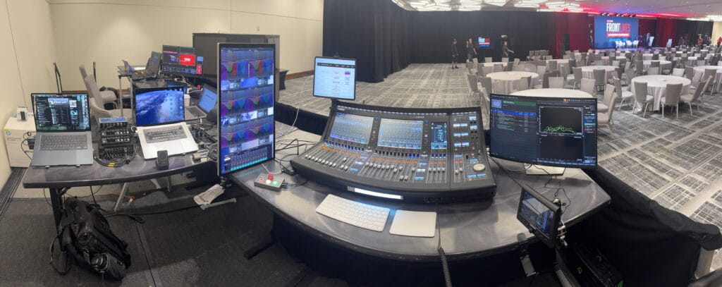
Before long cables and power supplies were hanging off the backside of the FOH L-positioned banquet table — like a bad Airbnb AV setup.
Getting FOH online started taking longer, and troubleshooting sometimes meant navigating cables as much as solving audio problems.
At some point I started having that nagging thought that the technical director might be timing me — even though they almost certainly weren’t.
“Geez, this Frost guy has been behind the console unzipping one gadget at a time for an hour… he does know we’re on a timeline, right?”
But the bigger issue wasn’t just my own setup time — it was what that meant for the rest of the crew during load-in.
Show labor is expensive, and during load-in there are a lot of moving parts.
When something stalls the build — whether it’s modifying the audio BOH footprint, cable paths that have to be changed, or coordination with another department — it can quickly ripple through the entire load-in.
Because of that, I try to remain present and aware of the audio team’s progress throughout the build. If my head is buried in setting up an elaborate personal FOH rig, not only does it consume my own time, it also takes my attention away from the bigger picture.
That distraction could easily coincide with the moment stagehands need guidance: rigging preparing to take audio to trim before signal testing and focus lines are tied on. It might also be the moment the carpenters start closing the hard set across the front of the stage, and the audio team needs to quickly pivot to run cables through the mouseholes before that access disappears.
For me, efficiency at FOH isn’t just about saving my own setup time — it’s about staying engaged with the overall build and making sure the entire team keeps moving forward.
Eventually I decided enough was enough and set out to consolidate everything into a compact fly rack.
⸻
The FOH Pelican Ecosystem
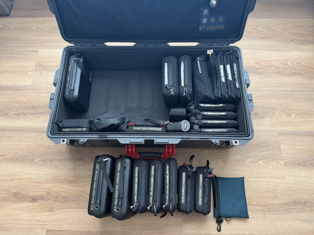
Before the rack build, my FOH infrastructure traveled primarily in a Pelican 1615, with a second Pelican Air 1535 carrying additional tools and accessories.
Inside the 1615 were the core components of my playback and VST system — interfaces, network hardware, adapters, measurement tools, and cables — each packed into its own labeled pouch.
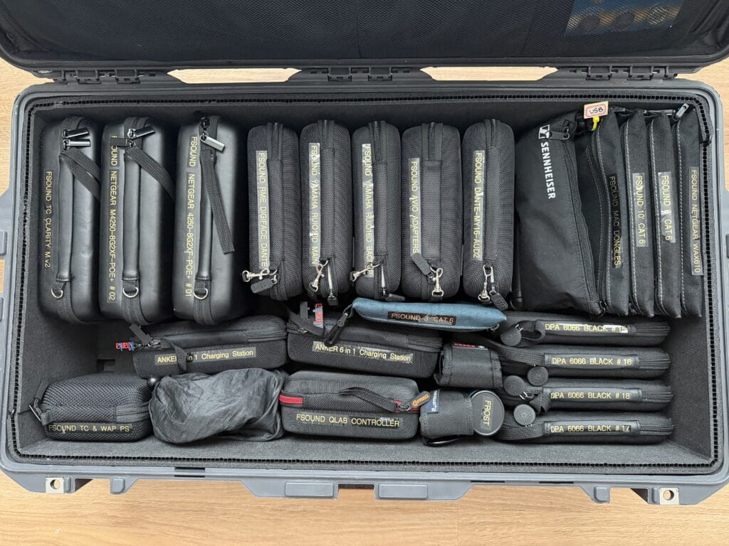
The 1535 handled many of the supporting items that tend to accumulate around a FOH position: clamps and mounts, second MacBook, iPad Pro, laptop stands, magnetic work lights, Bosch laser disto, Sound Bullet tester, Leatherman, and even a small bike-lock used to secure the Pelican cases to the FOH desk overnight.
The split between the two cases wasn’t just about organization — it was driven largely by weight. Once the 1615 crept past the airline’s 70-pound threshold, dense items had to be shifted into the smaller case to stay within limits.
Over time that pair of cases became a portable FOH ecosystem.
The goal of the rack build was straightforward:
Consolidate as much of that system as possible into a single deployable unit.
By permanently installing the playback and VST infrastructure inside the rack, a significant amount of volume and weight disappears from the Pelican 1615. This freed up enough space to move most of the items that previously lived in the 1535 back into the main case — with room to spare.
Some of that reclaimed space will now be dedicated to additional microphones. With the extra capacity I can comfortably travel with twelve DPA 6066 headsets, rather than the smaller kit I previously carried.
⸻
Starting With a Plan
Once I committed to the project, the first step wasn’t ordering gear — it was understanding the system.
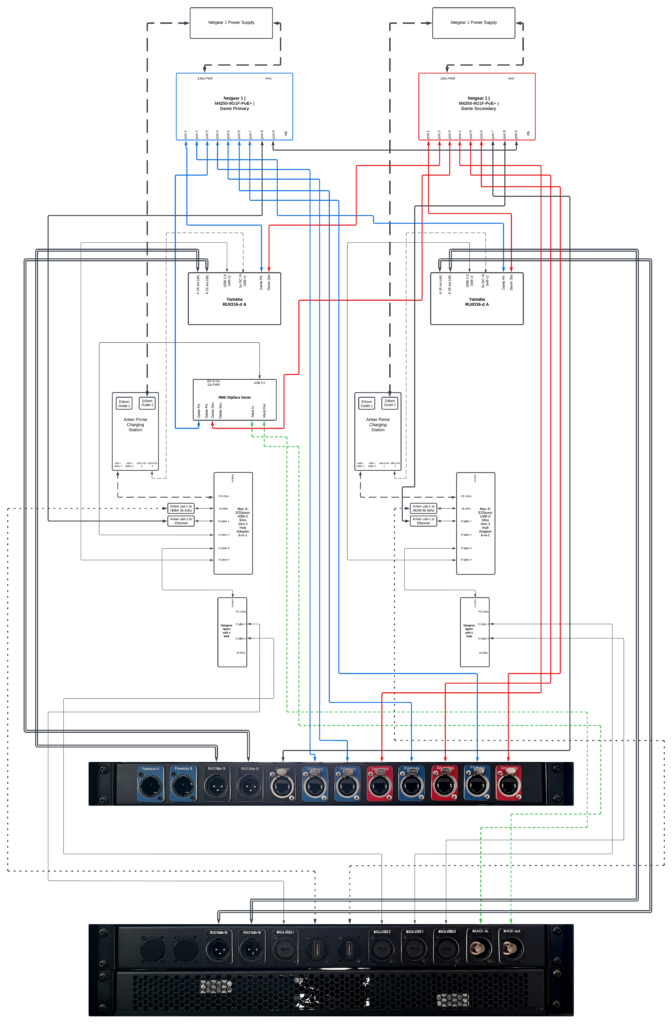
I opened Lucidchart and began mapping every connection that normally lived on my FOH table: Dante networks, USB interfaces, playback computers, control networking, and power distribution. From the very beginning the design included independent Dante A and B networks to maintain full redundancy.
Seeing the entire signal flow visually helped clarify what needed to live inside the rack and where redundancy needed to exist.
Only after the architecture started making sense on paper did the real experiment begin: sourcing parts and seeing what would actually fit inside a 3RU rack.
⸻
Version 1 — Conceptual Design
The first diagram represented the original concept for the rack, back when the plan was to have Savant Playback fabricate a custom laser-etched rear panel.
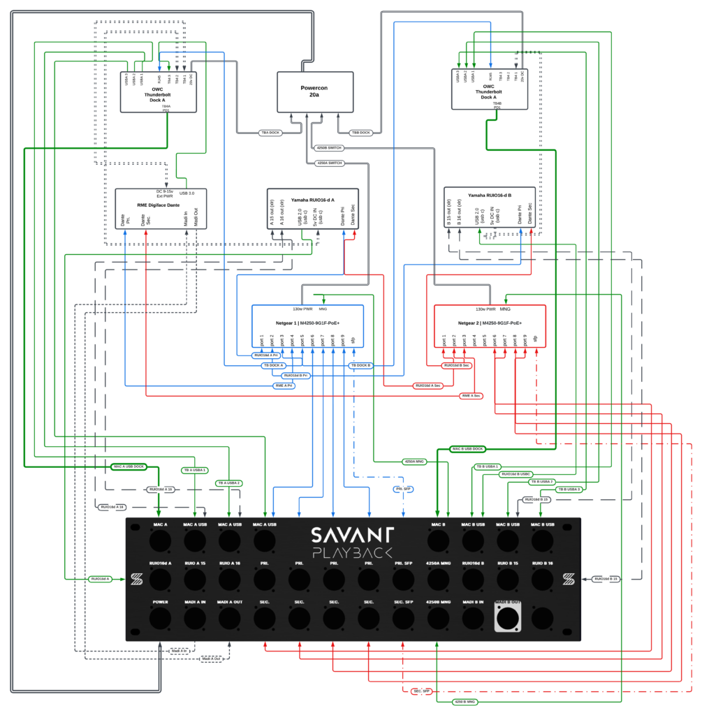
Even at this early stage the architecture already included several key elements:
• dual Netgear M4250 switches
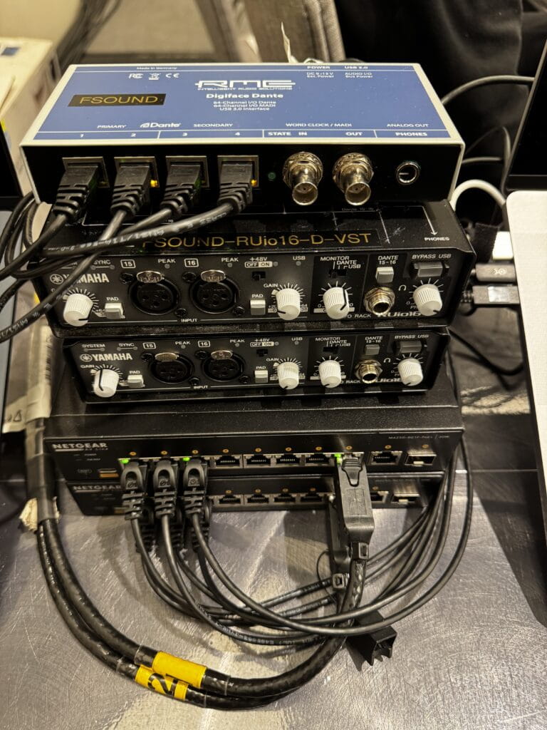
• Yamaha RUIO interfaces
• RME Digiface Dante
• redundant Dante networking
• playback and VST infrastructure
• optional MADI connectivity
The design was ambitious — but at this point it still existed entirely on paper.
⸻
Inheriting the Rack
For a while the project stalled due to an increased workload — and because Savant Playback had seemingly paused operations, leaving their website and online store offline.
Then my colleague and good buddy John Landsman of Directions Media upgraded his playback rig to a 4RU Waves LiveBox fly rack, which meant his existing 3RU Savant Playback rack was suddenly available.
With the custom rear panel option — and the availability of the 3RU rack itself — uncertain at the time, the project had started losing momentum. If it weren’t for John encouraging me to use his old rack, this build likely would have sat on the shelf quite a while longer.
That moment rebooted the project.
Suddenly the rack was sitting on my desk — a physical reminder that the idea was no longer just a diagram. It was quietly calling me to get back on the horse and finish what I had started.
And that meant the next phase of the project had to move from theory into reality. Every connector, cable path, and panel mount now had to fit inside a real 3RU rack with a fixed panel layout.
⸻
Version 2 — Adapting the Design to a Real Rack
Instead of commissioning a new panel immediately, I took a photo of the rack’s existing rear panel and began overlaying connection labels directly onto the image.
This made it much easier to visualize how the signal flow would align with the physical panel layout.
At that point the design began shifting from a conceptual diagram into something that had to work with real connectors, real spacing, and real hardware.

Version 2 also introduced several architectural changes as the design moved from theory into something that had to function reliably in the real world.
Key changes included:
• Power redundancy — Version 1 used a single power input. Version 2 introduced independent A and B power inputs so the rack’s redundancy extended all the way to power distribution.
• Fiber connectivity — Version 1 forwarded the Netgear switch SFP fiber ports to the rear panel. In Version 2 this was removed, since accessing those ports directly from the front of the switches remained practical.
• Computer connection points — Version 1 placed the MacBook A and MacBook B main USB-C tie-ins on the rear panel. Version 2 moved them to the front of the rack for easier access at FOH.
• MADI I/O simplification — Version 1 reserved two sets of MADI inputs and outputs to accommodate a future second RME interface. Version 2 reverted to a single MADI pair for the Digiface currently in the system.
• Thunderbolt expansion — Version 2 added a dedicated Thunderbolt passthrough connection to the rear panel for each computer.
These changes reflected a shift from a purely conceptual design toward a system that prioritized practical deployment, accessibility, and redundancy.
As these layout decisions were being made, I also began placing the core hardware that absolutely had to live inside the rack — the switches, interfaces, and power components — just to see how everything might physically arrange itself. Doing this early helped establish a rough interior layout and gave me a much better sense of how much space was actually available. That, in turn, began influencing the decisions for the remaining components that still needed to be ordered.

⸻
The Dock Experiment
With the core hardware roughly positioned inside the rack, the next challenge became figuring out how the computers would actually connect to the system.
My initial assumption was that the solution would be a pair of powered Thunderbolt docks — one for each computer. On paper this seemed ideal. A single device could provide USB ports, network connectivity, display outputs, and power delivery to the laptop all at once.
In theory it meant each computer could connect to the rack with a single cable and gain access to everything inside.
I auditioned two powered Thunderbolt docks: the OWC 11-port Thunderbolt Dock and the OWC Thunderbolt Go Dock. One used a large external power supply while the other housed the power supply internally, but once everything was accounted for they occupied roughly the same amount of space. After physically test-fitting them in the rack it became clear that neither was going to work — the total volume they required, dock plus power supply, was simply too large for the space available.
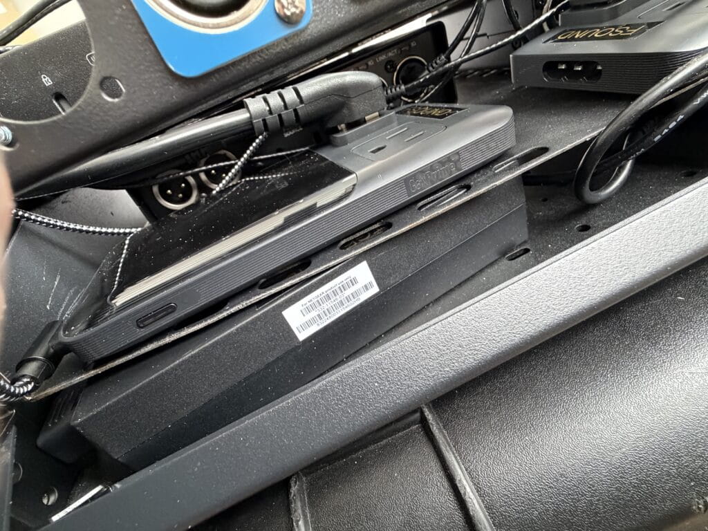
During this trial period I had also purchased two compact Anker power strips, since the Netgear switch power supplies required Edison connections anyway.
Once the Thunderbolt docks proved too large, I transitioned to using Anker Prime charging stations instead. They were only slightly larger than the power strips — essentially a flat power distribution device instead of a large cube-shaped one — but offered significantly more flexibility.
Each Anker Prime provided two USB-C ports with a combined 140 watts of power, two 5V USB-A ports, and two Edison outlets.
That opened the door to a different architecture.
Eventually I arrived at a much simpler solution.
A compact USB-C hub with power-delivery passthrough.
The device I ultimately settled on was the EZQuest USB-C Slim Gen 2 6-in-1 hub, which checked several important boxes for this design. One of the hardest requirements to satisfy was finding a hub with a detachable USB-C input cable, since I needed to port-forward that connection to a panel mount on the rack. Most hubs have short permanently attached cables, which would have made that impossible.
The EZQuest hub also provided a 100-watt power-delivery passthrough, a 4K 60 Hz display-capable USB-C port, and four USB 3.2 data ports sharing a combined 10 Gbps bandwidth pool.
To meet the remaining connectivity requirements, I added a USB-C ethernet dongle for control network access and a 4K 60 Hz HDMI adapter for video output.
At that point the port allocation was already tight. The Yamaha RUIO occupied one port and the RME Digiface Dante another, leaving one port remaining — and ideally I wanted at least two more: one for a wired QLab remote connection and another for miscellaneous peripherals that might need temporary access.
The solution ended up being another small hub.
I found a compact Vangree 4-port USB-C hub, also with a detachable upstream connection. This allowed me to branch the system one level deeper — essentially connecting a smaller hub to the primary hub.

Visually you can picture it as an octopus holding the hand of a smaller octopus to handle all the connections.
I was initially a little wary about introducing that many potential failure points — hubs, dongles, and adapters stacked together — but after thoroughly testing the configuration it proved to be completely stable.
And importantly, the entire solution occupied only a small fraction of the space the Thunderbolt docks would have required.
The power architecture also settled into a clean separation of responsibilities.
One USB-C port from the Anker Prime feeds the hub’s power-delivery passthrough to the computer, while one of the 5V USB-A ports directly powers the Yamaha RUIO interface using a short right-angle cable. That removes the RUIO from the computer’s USB bus power requirements and leaves the RME Digiface Dante as the only device drawing power from the hub.
Once the dock architecture was solved, the rest of the rack design could begin to take shape.
——
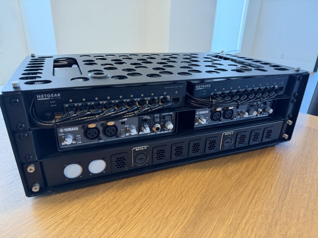
Version 3 — Final System Architecture
With the dock architecture, computer connectivity, power distribution, and USB infrastructure defined, the rest of the rack design began to settle into its final form.
At its core, the system functions as a redundant Dante playback and VST processing rack, designed to integrate quickly at FOH while providing access to the control network during setup and maintaining visibility into system health throughout the show.
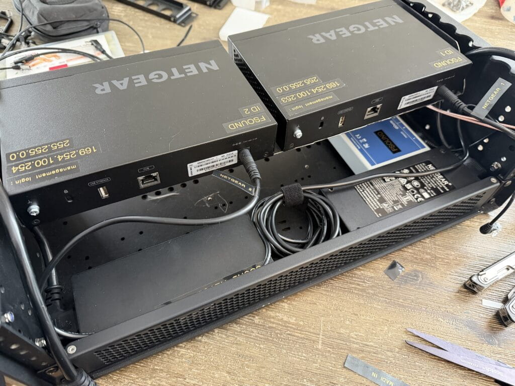
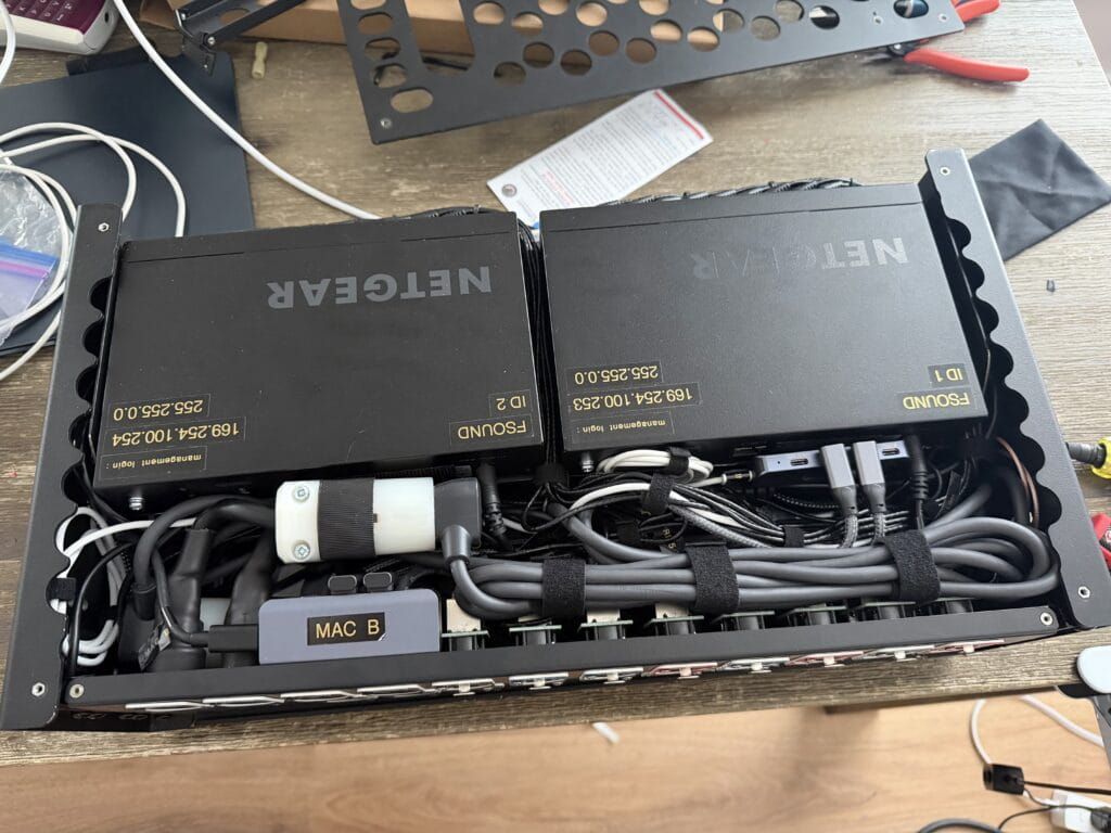
The rack is built around two Netgear M4250 AV Line switches, each serving a separate Dante network. One carries the Dante Primary network, while the other carries the Dante Secondary network.
In Dante systems redundancy is achieved by running two completely independent networks in parallel. Devices that support redundancy connect to both networks simultaneously, allowing audio to continue flowing even if one network experiences a failure.
Because of this, the two networks remain fully isolated from each other and operate on separate switches rather than being segmented through VLANs on a single device.
In addition to the Dante networks, both switches include a shared control VLAN on their final ports. This allows a single external control network — such as LA Network Manager or d&b ArrayCalc — to be introduced into the rack and made available to both computers.
One additional design decision involved how Dante Controller access is handled.
Rather than introducing the Dante Primary network directly into the computers through separate Ethernet adapters, I chose to rely on the RME Digiface Dante’s USB bridge for network access. As a result, the primary computer connected to the RME can see the Dante network and run Dante Controller.
For now the second computer doesn’t have direct Dante visibility, but once a second RME interface is added both machines will gain that access. In the meantime I still travel with spare Ethernet adapters if direct network access is ever needed.
One element from Version 2 that didn’t make it into the final build was the planned Thunderbolt passthrough on the rear panel. After searching for panel-mount options, I couldn’t find any D-type connectors that reliably maintained full Thunderbolt compliance. Rather than introduce a questionable link in the signal path, I removed the passthrough entirely. Any Thunderbolt connections — such as my Mac Studio Display — are now made directly to the computer.
While the rack does include MADI connectivity, it plays a relatively small role in the design. Most of my work takes place on Yamaha consoles where Dante is the dominant transport. The MADI ports exist primarily for the occasional scenario where I encounter a DiGiCo console.
The system also forwards the analog XLR outputs from the Yamaha RUIO interfaces to the rear panel, providing an immediate analog fallback if a console ever requires it.
By this point the system architecture itself was largely defined.
What remained was figuring out how to physically make everything fit inside a 3RU rack.
————
Refining the Physical Layout
At this stage John suggested another improvement that ended up being a huge quality-of-life upgrade during the build.
Instead of mounting everything behind a single fixed 3RU rear panel, he recommended switching to individual 1RU hinged panels. That way one side of each panel could stay screwed down while the other side could swing open on the hinge.
In practice this meant I could work on the interior of one rack unit at a time instead of removing an entire 3RU plate every time something needed to be adjusted.
It turned out to be a monumental improvement in ease of assembly.
Even with the hinged panels, however, a lot of the layout still required trial and error.
I spent quite a bit of time playing musical panel mounts while trying to make everything physically fit.
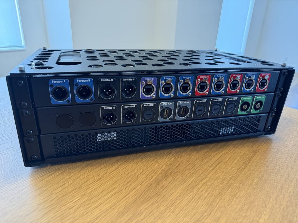
For example, some of the network cables I had planned to use turned out to be slightly too short to reach the leftmost EtherCON positions on the rear panel. Rather than replace the cables, I shifted the EtherCON panel mounts toward the right side of the rack where the lengths worked.
Another discovery came from the placement of the Netgear switch power bricks.
Once those were positioned in their most practical location inside the rack, it became clear that there simply wasn’t enough clearance behind the bottom rear rack unit to install panel connectors. Instead, I installed a vented panel in that space to allow airflow through the chassis.
The HDMI panel mounts also had to move during the process. Their internal connector housings extended farther into the rack than expected and collided with the Anker Prime charging stations. The only place they could physically fit was in the center position of the middle rack unit, where the geometry of the charging stations allowed enough clearance.
Another unexpectedly tricky part of the build was wiring the PowerCON True1 inputs.
Originally I had ordered a set of generic NEMA connectors to terminate the internal power cables. Once they arrived, however, I realized they were not designed to handle the 12-gauge power cable I was using. Beyond that, they simply felt cheap.
So I upgraded to Hubbell connectors, which were far better built and more appropriate for the application.
After wiring and heat-shrinking the connectors, the next challenge was figuring out how to physically place them inside the rack without the two connectors stacking on top of each other.

My solution was to intentionally make one cable about eight inches longer than the other so the connectors could sit in different areas of the rack.
The first attempt ended up being slightly too long, so I trimmed roughly three inches back off the cable and coiled the remaining slack into the bottom left corner of the middle shelf area.
Another small detail that ended up making a surprisingly big difference came from John during the build.
He came across a service from Redco Audio that allows you to order custom 3D-printed D-type panel labels in a variety of colors. Instead of relying on label tape, printed stickers, or having permanent labels laser-etched into the panels themselves, these inserts mount directly onto the outside of the panel using the same standard D-type screws that secure the connectors.
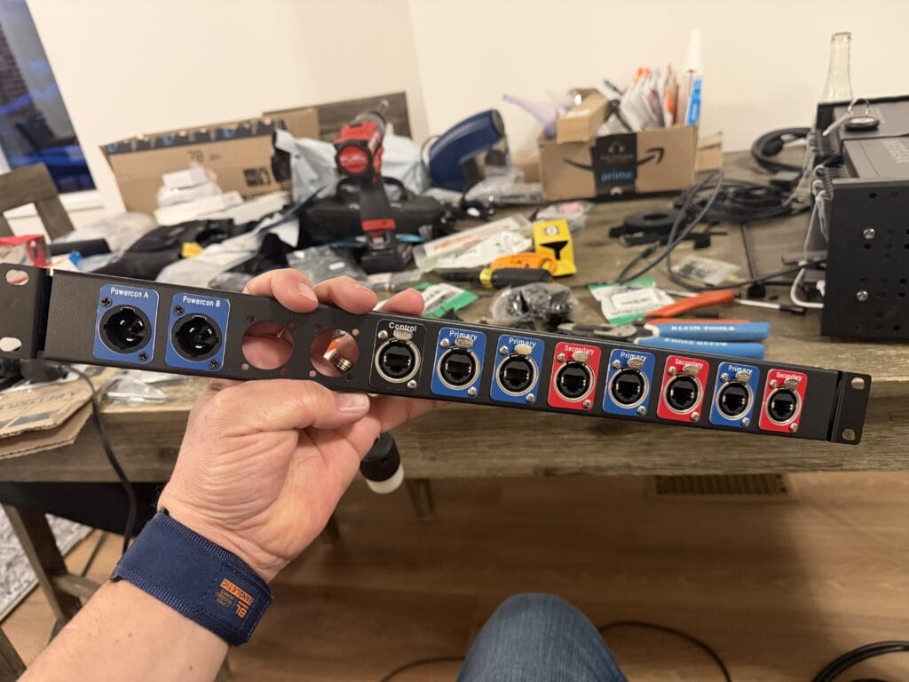
The added benefit is flexibility — if the rack ever changes in the future, all that’s required is ordering a new set of labels rather than replacing or modifying the panel itself.
It was a small upgrade, but visually it made a huge difference.
Suddenly the rack stopped looking like a DIY project and started looking like a real touring rack.
When I saw them installed for the first time, my reaction was simple:
“Now that looks profesh.”
——
The Cable Rabbit Hole
With the panel layout finalized and the rack finally starting to look like a real piece of touring equipment, the next phase of the project began.
Cables.
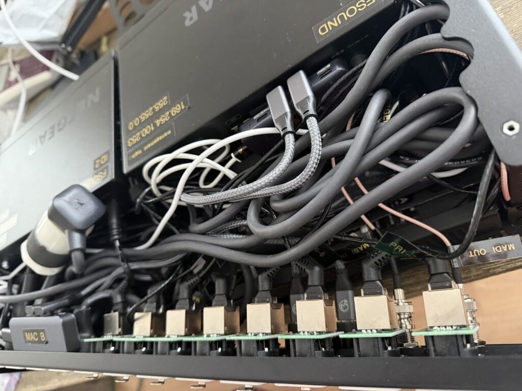
What looked clean and orderly on the outside hid a far messier reality inside the rack.
Because space inside a 3RU chassis is extremely limited, nearly every connection required careful thought about connector orientation, cable length, and routing direction. A straight connector in the wrong place could easily collide with another device or prevent a panel from closing.
So the hunt began for right-angle connectors wherever possible.
For a while my Amazon purchase history started to look like a catalog of oddly shaped cables.
One of the earliest examples involved the Netgear switch power bricks. I needed a short 90-degree IEC to Edison cable to run from the switch power supplies to the internal power distribution.
The first cable I ordered solved one problem but created another. It had a right-angle IEC connector, which cleared nicely, but the Edison end was straight and pushed the cable into the middle of the rack where it interfered with other wiring.
The second cable improved that situation with a right-angle Edison connector — but the angle was slightly skewed, sending the cable off in a direction that was just as problematic.
On the third attempt I finally found the correct combination: a right-angle IEC paired with a true right-angle Edison connector that directed the cable exactly where it needed to go.
USB-C cables introduced their own complications.
There are seemingly endless variations out there — 240-watt power cables, high-speed data cables, Thunderbolt 4 and 5, USB 3.2, 3.1, 3.0, and simple power-only USB cables. Some support high-speed data but not high power. Others support power delivery but fall back to slower data speeds. Some work perfectly in one direction and then mysteriously require flipping the connector 180 degrees before the signal passes correctly.
Sorting through the different specifications and figuring out which cables actually supported the required combinations of data, video, and power delivery was enough to make your head spin.
In some places I needed a right-angle USB-C connector on only one end, while the opposite end needed to remain straight so it wouldn’t block adjacent ports on the hub.
After searching through countless variations, I eventually had to concede in one location and simply use a standard straight 1-foot USB-C cable where I had originally envisioned a right-angle connection.
Networking cables added another layer of puzzle solving.
At one point John suggested trying right-angle Cat6 cables made by CableCreation with fully rotatable 360-degree connectors, which turned out to be incredibly useful — although not exactly cheap at around $9 per cable. Being able to rotate the connector after installation made it possible to route each cable exactly where it needed to go without wasting space inside the rack.
Even cable length became part of the equation.
In some patch points a 1-foot cable worked perfectly. In others it came up just a few inches short and had to be replaced with 18-inch or 2-foot runs in order to seat the connector properly without stressing the cable.
Designing the rack on paper took a few evenings.
Finding the cables that actually made it work took several weeks.
⸻
The UPS Store Got to Know Me
All of that experimentation had another side effect.
Amazon returns.
Every few days I would show up at the UPS Store with a stack of padded envelopes and small boxes heading back to Amazon — cables that were the wrong orientation, the wrong length, or the wrong data specification.
After a while the staff started to recognize me.
At one point I returned 25 items in a single visit, neatly stacked on the counter like a small mountain of cardboard and bubble mailers.
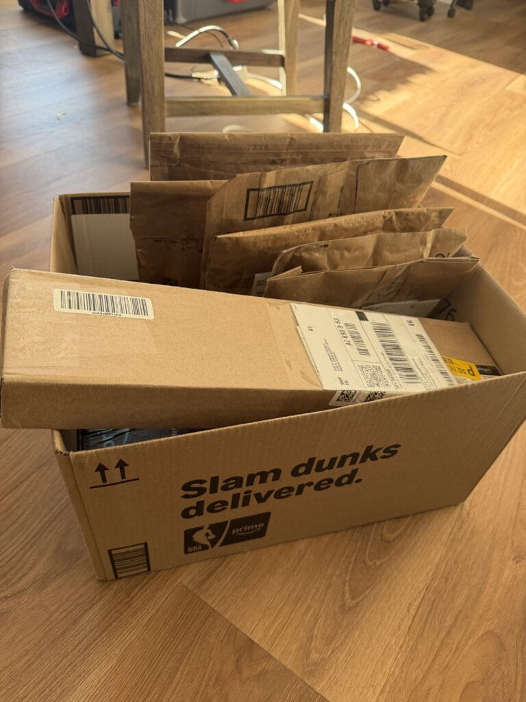
Later that afternoon my phone started buzzing with return confirmations about every 30 seconds until all 25 items were finally processed.
——
The 3RU Space Crunch
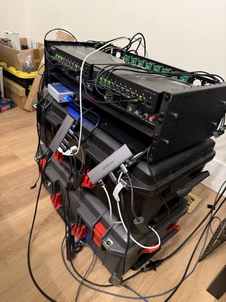
With the architecture finalized and the cables finally sorted out, the next challenge became obvious the moment everything started going into the rack.
Space.
On paper the design felt efficient. In reality, once power supplies, USB hubs, network switches, interfaces, and patch panels were installed, the available interior volume disappeared very quickly.
Originally I had envisioned the interior wiring looking something closer to an installation rack — neatly routed cables, clean tie-down points, and carefully labeled runs feeding each panel connector.
In my head it was going to look like cable management artwork.
Then I tried to close the lid.
That was the moment I realized I had been slightly optimistic about the available space inside a 3RU chassis.
As Mike Tyson once said:
“Everybody has a plan until they get punched in the face.”
The punch, in this case, was discovering just how little interior clearance remained once all the hardware and power supplies were installed.
At that point the priorities shifted.
Instead of chasing perfect cable aesthetics, the goal became much simpler:
Make everything fit.
Make it reliable.
Make sure the rack actually closes.
One design choice that significantly impacted the available space was the decision not to shorten the proprietary power cables for the Anker Prime charging stations.
Those cables are roughly five feet long, which is obviously far more length than needed inside a small rack.
It would have been possible to cut them down and terminate new connectors, but that introduced a different risk. If anything went wrong during the modification, I could end up with a damaged proprietary cable that might be difficult to replace.
And if the rack were ever reconfigured or the charging stations repurposed later, a shortened cable would make them far less useful.
In the end, preserving the original cables felt like the smarter long-term decision — even if it meant carefully coiling and managing several feet of extra cable inside an already crowded rack.
By the time everything was finally installed, the interior wiring was far from the perfectly organized cable architecture I had originally imagined.
But the rack closed, everything worked, and the system was solid.
Sometimes that’s the real victory.
——
Deploying the Rack
After months of diagrams, cable experiments, and careful packing, the final goal of the project was actually very simple:
Make FOH setup faster and cleaner.

On show day the rack travels inside a Pelican Air 1535, protected by custom internal padding. Once it arrives at FOH, the deployment process is dramatically simpler than the setup it replaces.
Instead of unpacking a dozen individual cases and assembling a small ecosystem of devices across the FOH table, the entire playback system now arrives fully wired and ready to go.
The setup sequence looks like this:
1.Place the rack on the FOH table
2.Connect PowerCON A and B
3.Patch Dante Primary, Dante Secondary, and the control network
4.Connect one USB-C cable to each computer
That’s it.
Both playback machines immediately gain access to everything inside the rack:
• Dante playback interfaces
• VST Rack Pro processing
• network connectivity
• control networking
• measurement tools
• USB peripherals
• power delivery
What used to require unpacking, routing, and troubleshooting a web of cables now takes only a few connections.
Instead of building out a workspace at FOH, the entire system now arrives as a single rack.
And perhaps most importantly, it allows me to walk into FOH, plug in a handful of cables, and focus on the show instead of building my workstation.
——
Design Philosophy
Several principles guided the design of this rack.
True redundancy
The system uses two completely independent Dante networks, each with its own switch and power source, alongside two independent playback systems. If the primary network or playback chain fails for any reason, the secondary system continues passing audio without interruption.
Minimize FOH setup time
The entire purpose of the rack is to reduce the time spent assembling infrastructure at FOH. By arriving fully wired and preconfigured, the playback system can deploy in minutes instead of requiring dozens of cables and adapters to be unpacked and connected individually.
Accept practical compromises
Like most fly rack designs, the interior wiring ultimately became a balance between elegance and practicality. Reliability and serviceability always took priority over cosmetic perfection.
At the end of the day, the rack isn’t meant to impress anyone when the lid comes off.
It’s meant to disappear into the background and let the show happen.
——
Future Expansion
Although the rack is fully functional in its current form, it was intentionally designed with room to grow.
At the moment the MADI portion of the system is not redundant, but space has been reserved both physically inside the rack and on the rear panel for a second RME Digiface Dante interface.
The long-term plan is to expand the system alongside a future computer upgrade. A new MacBook Pro will become the primary playback and VST processing machine, while my current M2max MacBook Pro will transition to the backup, and my MacBook Air will be gifted to my wife — our usual household upgrade path.
Once that upgrade takes place, the architecture will evolve into a fully expanded configuration.
Current interface roles
Yamaha RUIO A
VST Rack Pro
Yamaha RUIO B
QLab Backup
RME Digiface Dante A
QLab Main
Smaart
VOG Recording
Planned expanded configuration
Yamaha RUIO A
VST Rack Pro Inserts 1–16
Yamaha RUIO B
VST Rack Pro Inserts 17–32
RME Digiface Dante A
QLab Main
Smaart
VOG Recording
RME Digiface Dante B (future addition)
QLab Backup
BGM Playback
In shows that require 16 inserts or fewer, the two RUIO interfaces could also be configured in a main/backup scenario rather than simply doubling the insert count. In that case the console inserts could be patched to both systems simultaneously, with the backup VST chain bypassed until needed.
The exact routing logic will evolve as the system grows, but the goal remains the same: build enough flexibility into the architecture that the rack can adapt to different show requirements without requiring a redesign.
By leaving space in the rack for the second Digiface now, the system can expand later without rebuilding the entire system.
Sometimes the best rack design decision isn’t about what goes into the rack today — it’s about what you intentionally leave room for tomorrow.
——
Final Thoughts
In the end, the rack replaces what used to be an entire Pelican case worth of FOH infrastructure.
Interfaces, switches, playback hardware, power distribution, and control networking now live inside a single compact system that can be deployed in just a few minutes.
What once required unpacking multiple cases and assembling a small ecosystem of devices across the FOH table is now reduced to a handful of connections.
The forest of cables that used to grow behind my mix position has been replaced by a single rack.
But the real benefit isn’t just aesthetics.
The rack allows me to spend less time assembling personal infrastructure and more time staying engaged with the overall show build — working with the audio team, coordinating with other departments, and keeping the production moving forward.
In live production environments where schedules are tight and labor is expensive, that time matters.
And while the rack will likely continue evolving — new computers, additional interfaces, and expanded processing — the foundation is now in place.
The goal was never just to build a rack.
The goal was to build a system that lets me walk into FOH, plug in a few cables, and get to work.
——
About the Author
Brian Frost is a freelance corporate audio engineer with over two decades in live event production. He specializes in large-scale corporate and hybrid events where routing architecture matters as much as sound quality. Known for designing flexible systems that scale with modern show demands, Brian works nationally and is based in Utah.
Learn more at fsound.net